Operators
Manual for the alternate
firmware for the Montreal Doppler
II and Doppler III units.
Important notice - please read:
This firmware was based on code originally written by Jacques for
the Montreal Doppler II. Many new features have
been added and most of the code has been extensively rewritten without
Jacques' direct involvemen: Please read the disclaimer. For more
information, use the contact information
at the bottom of this page if you have any questions.
Operational differences between the
Montreal Doppler II and Doppler III hardware:
The Montreal Doppler II and Doppler III hardware are very similar
to each other - but with a few important differences:
The Doppler II uses 4 pushbuttons to navigate the
menus and select various items whereas the Doppler III
has a single pushbutton and a potentiometer to do the same
functions.
The Doppler III has a "Roanoake-type" switched capacitor
filter for additional filtering. The Doppler II does not
have this filtering - but the addition of such a filter is
described on the Switched
Capacitor Filter page and is highly
recommended!
The Doppler III has audio level metering taken at a point
prior to the narrowband switched capacitor filter. This
metering provides an immediate response to signal level changes
and may be used to set the audio level on the unit in a
repeatable manner. The Doppler II has audio metering - but
this is derived from the signal processing and may be slow to
respond to changes, particularly if the integration level is set
fairly high. The addition
of similar circuitry to the Doppler II is highly
recommended!
The Doppler III has a compass rose display driven by a
synchronous serial output ("SPI" - type.) This replaces
the on-screen 36-point compass rose that was used on the Doppler
II unit and makes for a much easier-to-read intuitive
display. This firmware allows the implementation of this
display on a Doppler II unit after appropriate
modification. This firmware supports the use of this same
display with the Doppler II.
The original firmware for the Doppler II and Doppler III have
slightly different rotation frequencies: The Doppler II
operates at 500.8 Hz whereas the Doppler III operates at
approximately 499.3 Hz. This alternate firmware
operates at 500.8 Hz for both the Doppler II and III, but a
version operating at 499.6 Hz is available by special
request.
Firmware installation:
There are two versions of this firmware: One for the
Montreal Doppler II unit, and another for the Montreal Doppler III
unit. While it is theoretically possible to have one piece
of firmware that will automatically detect which hardware is being
used, program space limitations prevent this, so two different
versions are available, with the hardware platform being selected
at compile time.
Both versions have exactly the same features, with the sole
exception of a larger number of choices for integration/average
settings being available on the Doppler III: This is
possible only because the menu potentiometer makes it practical to
choose amongst a larger number of options whereas on the Doppler
II, that number of selections would involve tedious
button-pressing to go through all of the possible choices.
Another difference is that on the Doppler II it is possible to
perform a complete EEPROM wipe at any time, resetting all
parameters to default.
Installation of the new firmware involves only the replacement of
the 40-pin processor: No other changes are made, and one may
put the original firmware back at any time. The only
possible caveat to this is that on the Doppler II, if the
modifications to add the audio level meter and/or compass rose are
made and the old firmware is installed, these pins may be
floating at an indeterminate input level and cause the processor
to draw a few extra milliamps of current unless they are tied
either to ground or +5.
Figure 1- The
screen showing the compile date of the firmware for versions
older than 7A. This may be used to determine
which version of firmware is installed. Starting
with version7A this screen is no longer used
as the version number is always displayed on the startup
screen.
Modification of the Doppler II hardware:
If you use the new firmware in a Doppler II unit, you have
several options:
One may simply plug the newer processor into the existing
socket and expect improved performance and capabilities, making
no modifications at all.
Some of the more useful features do require
simple board modifications and minor circuit additions.
Details on modifying the Doppler II to add audio level metering,
a drive signal for the switched-capacitor filter, and the
compass rose output may be found on the Doppler II Modification
page. Additionally, "Adaptive Filter" control of an
outboard 8-capacitor "Roanoke" type filter and a "Stop Rotation"
control may be added as well - see modifications noted on this
page.
Modifications of the Doppler III hardware:
You also have a few options with respect to the Doppler III unit and
new firmware:
For the most part, no modifications are necessary to use most
of the features.
If you wish to implement the "Adaptive Filter" control
8-capacitor "Roanoake" type filter or the "Stop Rotation"
switch, minor circuit additions will be required. Details
of these modifications are found near the end of this page!
Power up:
The bootup cycle will display "Mont Doplr II-CT" or "Mont Doplr
III-CT" (depending on hardware) followed by software credits, and
then it will display the main screen. This cycle takes about
2 seconds, allowing power supply voltages and filters to
stabilize.
Note on firmware version 7A and newer: On
these newer versions of firmware, the firmware version is
displayed on the main startup screen sequence and the compile date
is no longer shown. Those versions using the PIC18F4620
processor will have a "+" symbol after the version number.
Checking compile date (versions prior to 7A only):
On both the Doppler II and Doppler III units, the firmware
compile date may be checked as follows :
On the Doppler II, press and hold the CENTER TWO buttons while
turning on the power.
On the Doppler III, press and hold the button while turning on
the power.
Again, on newer versions, this information is displayed on
power-up.
During startup, the date of compilation will be shown
briefly: No saved settings are altered when this done
except on the Doppler II when it detects a new modification (see
next section.)
Doppler II only:
On the Doppler II, powering up with the center TWO buttons
pressed will cause an additional screen to be displayed,
(following the date on versions older than 7A) showing the
detected status of the audio level metering, the drive for the
switched-capacitor filter, and the SPI interface for the compass
rose.
If the displayed status is "1" (as shown in Figure 2)
that indicates that the firmware has detected that the modifications to add these
options may have been completed, and a "0" of the circuit
board traces appear to be in their original configuration.
All that is done is to check to see if the traces on the
circuit board have been cut and it cannot actually tell if the
audio level, compass rose or switched-capacitor filter hardware
is really present.
EEPROM clear (Doppler II only): If all four
buttons on the the Doppler II are held down during powerup, the
EEPROM (containing user settings) is wiped. This is followed
by the display of the compile date (on versions older than 7A)
and the display of the audio level metering. This is NOT
available on Doppler III.
Important note (Doppler II only):
If a modification to use the audio level metering, the
switched-capacitor filter, and/or SPI output (for the compass
rose) is made, you must force a display of either
the software date or do an EEPROM wipe before
the modifications are
detected! It is only if the
"detected hardware status" screen is displayed that an attempt
is made to detect any modifications!
Figure 3 - Main
display before any bearing data has been
received. The asterisks (***) will be replaced with
bearing information and the signal quality information will
appear below the bearing.
Main Display:
Initial display:
After powering up, the main display will appear see Figure
3. If no bearing data has yet
been received, asterisks may be displayed instead of
numbers. This can also occur when exiting the menu system and
the display has not been updated (because of quality/audio level
gating.)
Note: If there is audio present on the input
when the unit is powered up, random bearing data may be displayed
and you may not see the asterisks. A random bearing
may also be displayed on powerup as the circuitry may not have
fully stabilized by the time the powerup cycle is completed.
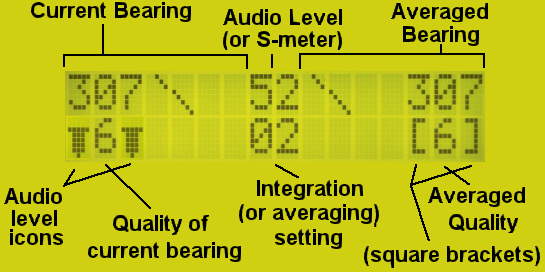
Explaining the display:
The display will simultaneously display the current
bearing (on the left)AND the averaged
bearing (on the right) and their respective signal
qualities in both numerical and graphical
format.
Figure 4 - The
arrangement of the main display showing the location of the
various data/status indicators. Note the "audio level"
icons surrounding the quality reading of the current
("integrated only") bearing: This means that the
buttons/knob will adjust the integration level. Note
also the diagonal bars on the left and right, which are the
compass rose displays for the "current" and "averaged"
bearings, respectively. (see text)
Figure 4 shows a typical display:
Both the "current" and "average" happen to be showing a
bearing of "307" degrees and a quality factor of "6".
Often, the two displays will show different readings -
particularly if either the transmitter or receiver is moving.
The diagonal line is the 16-point graphical compass rose,
showing the respective bearing, in graphical format, to the
nearest 11.25 degrees. Note: The cardinal
points (North, South, East and West) are displayed using
"double" lines (see an example of this in the AF GATE description, below.)
The numerical "Audio Level" reading (top, center) may be
configured to show a number from 0 to 99 that could be used to
represent an S-meter reading, field strength, or even battery
voltage. If the audio level is too high, this will display
"OL" to warn the user of possible audio input overload - even if
set to display the S-meter reading.
The center-bottom number show the current setting of the
integration or averaging - see below.
Surrounding the signal quality (on the left side, in this
case) are icons that represent audio level. As the audio
level increases, these icons get taller and wider. This
same location can also indicate whether the "audio
gating" or "average clear"(see
below) is currently in effect. Note:
This feature is available on the Doppler II only if
the audio level metering modification has been made.
Comment: On versions 7A and newer,
the "Square" brackets ([]) around the quality reading will be
replaced with a "greater-than" and "less-than" sign (<>) if
pin
5
of
the
main
processor is disconnected from the +5 volt supply and is available
for use with the adaptive filter - read about this
under the "Average Clear"
description.
The difference between the "current" and
"averaged" bearings:
The "current" bearing:
On the left side of the display is the "current" or
"instantaneous" reading. This reading has had applied to it
no averaging and in those cases where the bearing is
being degraded due to heavy modulation and/or multipath, it will
be seen to change seemingly randomly. It is possible to
"smooth" this reading somewhat by applying integration
(described below) that accumulates data from several
readings. Because approximately 20 readings are taken each
second, the update rate will slow by the amount of integration
applied. This is done in blocks, simply by summing the raw
data "N" types, with "N" being the amount of integration, so
setting the integration to 1 will yield 20 readings/second, an
integration of 4 will produce 5 readings/second, and so on.
The "averaged" bearing:
On the right side of the display is the "averaged" bearing.
This bearing is based on the processing of the present and past
"current" bearings and applying a sliding average
to the result. Because multiple past bearings are used and
the result is "weighted" according to bearing quality, this
portion of the display can be significantly "smoothed" and there
is the increased possibility that even if individual "current"
bearings are inconsistent, that the averaging will help identify
trends.
The effects of the "Integration" and "Averaging"
settings:
Integration:
Internally, 20 readings are taken each second. If the
integration setting is "1" (e.g. NO integration) then each bearing
is displayed as it is received.
Adjusting the integration/averaging on the
Doppler III using the knob.
As mentioned, when on the main display, the knob
adjusts the amount of integration (or averaging -
depending on setting) to be used. There is one
potentially confusing aspect of which the user should
beware, however:
The current setting of the knob is saved when the
button is pressed-and-held. This "saved" setting
is restored when the user exits the menu and on powerup.
Here's the confusing part: Because the
user uses the knob to adjust various settings within the
menus, the knob may not be in the same position
that it was before entering the menu system - but the
setting of the integration (or average) will still
revert to the saved setting - at least until the user
changes the knob setting again.
What this means is that if you'd set the integration to
16 (a value roughly correlating with mid-rotation) and
you entered the menu system, that value would be
saved. To exit the menu system, however,
you must select the "exit" icon which involves turning
the menu pot all of the way to the end of
rotation. When back in the main display, you'll
see that the setting is still 16 - even though
the pot may be rotated all of the way to the end, which
would mean a far different value. It will "revert"
to the pot's actual setting when the user turns it
again.
(Did any of that make sense?)
Having a higher integration rate also means that the display
update is slower: If the integration rate is set to
"8" then the new readings are displayed only after 8 readings have
been collected, resulting in about 2.5 readings per second.
Integration is useful for "smoothing" out noisy signals and/or
slowing the display update rate to a more manageable level.
Note that the effects of the integration aren't quite the same as
averaging as the raw data is simply accumulated for a longer
period and the effects of rapid changes during the integration
period - including those that might skew the data - are simply
lumped in.
The "Integration" ability in this firmware is intended mostly to
alow the slown down the display update and to provide a modicum of
"averaging" of noisy data. Although the unit can be set for
a large number of integrations, it is not
recommended that a setting of more than 8 be used as this slows
the unit's response to signal! Typically, one would use
an integration setting of 1 or 2.
Averaging:
This firmware supports a "sliding average" that takes from 2 to
32 of the most recent "current" readings and
averages them together (one of these 2-32 readings being the current
reading.) This has much the same effect as integration,
except that it is updated at the same rate as the integrated
bearing - but "smoothed." Because the newest reading is
included and the oldest is discarded, increasing the averaging
setting does not slow down the update of the display as the
integration setting does, but it does slow the response
of the display to changes in signals!
Also consider exactly what sort of information comprises
the "averaged" bearings: They take into account not only the
phase of the bearing, but the quality as well. When it comes
down to it, an "averaged" bearing is a close approximation to a
software simulation of the 8-capacitor "Roanoake"
filter. What this means is that even if you turn the
"Damping" potentiometer (assuming that you have added it)
to minimum damping (a "fast" response) you will still get much of
the same effect of having a switched-capacitor filter. With
the "integration" turned off (set to "1") the effect of 32 points
of averaging is less than that of the switched capacitor filter's
damping set to "maximum" - but it does a very good job of
"smoothing" out noise.
With the averaging being under software control we have
additional flexibility when it comes to how to handle the data
that we receive. For example, with the "Average
Clear" function you can have a mixture of some of the
advantage of a very fast response to received bearings yet some of
the "smoothing" and noise-reduction of a higher average
setting. As mentioned elsewhere, one can configure the
"Average Clear" to erase the "average buffer" a specified time
after the signal being received disappears. When the signal
reappears, the software does not require that,
assuming that the "average" setting is 32, that 32 readings arrive
before the average is displayed, but rather it will display the
average for the number of bearings that have been received
thusfar. So, if you receive a signal that lasts only 200
milliseconds, you can expect to have up to 4 readings averaged
together and the result of those averages will be displayed.
One obvious advantage of the averaging is that if the integration
rate is set to 1 (e.g. no integration) you still get an update
rate of 20 readings per second. If the averaging is
set to 32, you get the same "noise reduction" effect as having an
integration setting of 32, but the readings appear continuously,
rather than appearing in "chunks" at a rate of just one reading
every 1.5 seconds as would be the case were the integration set to
32.
Keep in mind that the "Current" (integrated)
bearing is the source of readings for
the "Average Bearing." What this means is that increasing
the integration will not only slow down the update rate of the
average bearing, but the final result will be that the number of
readings taken will be multiplied.
For example: Suppose that you set the integration rate to 8
(about 2.6 readings/second) and the integration to 32. In
reality, the averaged bearing/quality being displayed is based on
the past 256 readings (8 * 32) and the averaged bearing
includes bearings that were taken over 12 seconds ago (that is, at
2.5 readings per second and 32 readings being averaged, it takes
12.8 seconds for the "oldest" reading to be discarded.
Another example is that if the integration level is set to 64 and
the averaging is set to 32, the displayed average is based on
contributions of the most recent 2048
readings. Note that this also means that the reading will
include data received around 100 seconds ago (assuming continuous
updating, of course.)
One final comment:
ONLY "good" readings (those above the pre-set
quality threshold and those allowed by the AFGATE
setting) actually contribute to the averaged
reading: "Bad" readings are completely ignored!
Note: The firmware using the PIC18F4620 device
allows up to 64 averages to be taken.
Adjusting the amount of integration or
averaging:
It is possible to adjust both the amount of integration and
averaging being applied - but not at the same time.
Experience and testing has shown that one would usually set the
integration value to one's taste (usually a value of 1 or 2) and
then adjust the averaging as the situation demands.
Integration or Averaging is adjusted by using the
pushbuttons on the Doppler II or using the knob on the Doppler III
- but which parameter (integration or averaging) is
adjusted from the main display depends on a setting in the "AFGate
Menu" (see below) but this information may be
discerned from the main screen.
Figure 5 - This
display shows the "audio level" icons around the quality
level on the average display. This indicates
that the buttons on the Doppler II (or knob, in the case of
the Doppler III) will adjust the amount of averaging
being done: 32, in this example.
Taking a look at the display, notice that the quality factor of
the averaged reading is surrounded by the audio
level icon but the quality factor of the current
reading is surrounded by square brackets. It
is the number that has the audio level icons that may be
adjusted (using the buttons or knob) while in the main
menu.
In the case of the picture, with the audio level icons
surrounding the averaged quality, we know that
pushing the buttons (or turning the knob, as in the case of the
Doppler III) will adjust the averaging AND that the
number shown in the center (on the bottom) is the current averaging
setting.
If the audio level icons are surrounding the quality factor of
the current bearing (as shown in the picture with
the labels at the top of the page) then it is the integration
that is adjusted by the buttons/knob.
Button operation in the main
display:
Doppler II - The buttons operate as follows:
Button #1 (typically, the left-most button):
If the audio level icons surround the quality reading of the
current bearing and square brackets surround the
quality reading of the averaged bearing, this
button resets the integration to 1 (e.g. NO integration.)
If the icon surrounds the quality reading of the averaged
bearing and square brackets surround the quality reading of
the current bearing, this button clears/resets
the average.
Button #2:
This button decreases the amount of averaging or
integration, depending on mode. Note: When
the averaged bearing is changed, the entire history of the
averaging buffer is cleared.
Button #3:
This button increases the amount of averaging or
integration, depending on mode. Note: When
the averaged bearing is changed, the entire history of the
averaging buffer is cleared.
Button #4 (typically, the right-most button):
This button causes the calibration menu to be displayed.
Pressing buttons 2 and 3 (the center 2 buttons)
simultaneously:
A bearing is sent out via the serial port. Note
that this must be configured in the APRS menu - see below.
Doppler III - The button and knob operate as follows:
The knob:
If the icon surrounds the quality reading of the current
bearing and square brackets surround the quality of the averaged
bearing, the knob adjusts the amount of integration.
If the icon surrounds the quality reading of the averaged
bearing and square brackets surround the quality of the current
bearing, the knob adjusts the amount of averaging. Note:
Whenever
the
averaging
setting
is
changed, the averaging buffer is cleared.
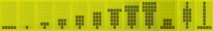
Figure 6 - This display
shows various displays of the "audio level" icons. From
left to right: 1: Gated audio (GATE level set to
1) 2: Audio level of 0 (GATE level
set to 0) 3: Audio level of 1 4:
Audio level of 2 5: Audio level of 3
6: Audio level of 4 7: Audio
level of 5 8: Audio level of 6 9:
Audio level of 7 10: Audio level of 2, but
a GATE setting of 3 or higher 11:
The icon displayed on a Doppler II without the added
audio-level circuitry. 12: The indicator
(vertical line) that shows that the "average clear" is active.
The button:
A momentary press of the button sends a
bearing out via the serial port - if appropriately
configured in the APRS menu.
Pressing and holding the button for more
than approximately one second will enter the menu system,
starting with the calibration menu.
The audio level icons:
Surrounding one of the quality level displays (the one that may
be adjusted by the knob/buttons) is the audio level icon. As
may be seen in Figure 6, as the audio level increases,
this icon gets both "taller" and "wider."
The left-most icon in the picture shows the "audio gated"
condition by the presence of the horizontal line at the bottom of
the icon. In this example, the GATE level (read about the GATE setting below)
is set to 1. The second icon from the left shows an audio
level of zero but without the gating active (e.g. a
GATE level setting of 0.)
The audio level icons will display the audio level despite the GATE
setting. The second icon from the right shows an audio level
of 2 but with the audio gating active, hence the line at the
bottom - this situation could happen with a GATE setting
of 3 or higher.
Note: If you are using an unmodified Doppler II unit
(no audio level metering added) neither the audio level icons or
the AFGATE feature is available then icon #11 (next to the
one on the far right) will be displayed instead.
"Why have both the audio level icons
AND the audio level readout?"
These two readings are from difference sources and can
indicate different things:
- The audio level icons are derived from the voltage
from the diode/capacitor circuit connected to the output
of the first filter (before any switched capacitor
filter.)
- The numerical reading is based on the audio that the
main processor gets - audio which, in the case of the
Doppler III (or a Doppler II with the added switched
capacitor filter) may have passed through the switched
capacitor filter.
This means that the numerical indicator is less
affected by noise and/or modulation on the signal and
will probably read lower as the signal being received
degrades. As the signal continues to degrade the
switching tone becomes more diluted with noise which
means that the audio level icon may still read a high
signal but the numerical value drops.
Note also that as the integration rate is increased,
the update rate for the numerical value slows down,
too: The update rate for the audio level icons is
not similarly affected and this is where the
"AFGATE" threshold is derived from.
(Also, I couldn't think of anything else to put
there...)
Also note that the icon at the far right shows the "active"
indication of the "Average Clear" function see below.
The Menu system:
The major difference in operation of the software between the
Doppler II and Doppler III has to do with the user
interface: The Doppler II has four buttons
while the Doppler III has just one button and a
potentiometer.
On the Doppler II the menu system may be entered by
pressing button #4, while on the Doppler III one
presses-and-holds the button for approx. one second.
Selecting menu items:
Doppler II:
Buttons 1-4 are typically placed under the display and they
(roughly) correlate with menu items on the display: In all
cases, pressing button #4 by itself moves to the next
menu/display. Note that some functions on the Doppler
II require that more than one button be pressed at the same
time.
Doppler III:
The potentiometer moves the blinking cursor to the desired
item and pressing the button selects/changes that item. In
all cases, moving the cursor to the far right and then pressing
the button moves to the next menu/display.
The Calibration Menu:
This menu is used to calibrate the direction shown on the display
with respect to the actual bearing. If you are in a vehicle,
this is currently set (often using the "AUTO" function) such that
straight ahead is "North" (0 degrees.) If the unit is used
in a fixed location, one would typically calibrate the unit such
that the bearings correlate with true-north bearings on a map.
Figure 7 - This menu
is used to calibrate the direction shown on the display with
respect to the actual bearing. This picture shows the
display from the Doppler III, with the cursor (a line) under
the arrow on the bottom-right. (The Doppler II does
not have a cursor.)
Provisions are provided to increment the bearing in one or
ten degree increments. The calibration value ranges from 0
through 359, "wrapping around" to 0 at 360.
Doppler II:
Button #1: Return to the main display: This button
is typically located to the left of the display, above or below.
Button #2: Decreases the calibration direction
by one. This button is typically located toward the
middle-left of the display.
Button #3: Increases the calibration direction
by one. This button is typically located toward the
middle-right of the display.
Button #4: Moves to the next menu (e.g. the APRS
menu.) This button is typically located to the right of
the display, above or below.
Buttons 2 and 3 simultaneously: This is "AUTO"
where the most current direction is assumed to be
where "zero" degrees ("due North") should be. This is
useful for calibrating "straight ahead" in a vehicle.
(These two buttons would typically be located above or below the
word "AUTO.")
Buttons 1 and 2 simultaneously: This decreases
the calibration direction by 10 degrees. (These two
buttons would typically be located above or below the "10" on
the left side of the display.)
Buttons 3 and 4 simultaneously: This increases
the calibration direction by 10 degrees. (These two
buttons would typically be located above or below the "10" on
the right side of the display.)
Doppler III:
The menu potentiometer is used to place the cursor on the
items mentioned above, and pressing the button changes/selects
that item.
Note that the arrow on the far left is selected to return
to the main display while the arrow on the far right
(above the cursor) is used to move to the next menu (e.g. the
Antenna menu.)
Important note about the AUTO function:
For software versions dated prior to August 28,
2005 (Version 6H and earlier): The AUTO
function may be used ONLY when a signal is present!
This function takes the CURRENT reading and sets
"Due North" (zero degrees) to that bearing. Please
note that if there is NO signal
present, the result will be a random bearing being used for the
AUTO setting.
For software versions August 28, 2005 and later
(Version 6I and later): The code has been
changed to use the last-available averaged
bearing for the AUTO setting. This allows for
averaging of the "calibration" bearing as well as permitting the
most recently obtained averaged bearing to be used - even if the
signal has disappeared.
Figure 8 - This menu is
used to configure and test the antennas.
The antenna menu:
NUMBER - Number of antennas:
This "NUMBER" menu item is used to configure the type of
antenna system being used. This firmware supports the
following types of antenna switching:
4, 6, or 8 antennas may be switched.
Positive or negative switching. If positive
switching is selected, the antenna is "selected" of the voltage
is high (5 volts.) If negative switching is
selected, the antenna is "selected" if the voltage is at ground.
NOTE: If the setting of 4 antennas is
selected, differential antenna drive is available. In this
mode, outputs 1-4 have signals with the displayed polarity (+ or
-) while outputs 5-8 always have the opposite polarity
signal of outputs 1-4.
ROT - Antenna rotation direction:
The "ROT" item selects the direction of antenna "rotation"
- either clockwise (CW) or counter-clockwise (CCW.) What
your particular antenna requires depends on which order the
individual antennas were connected. If this is backwards,
bearings that are left or right of the calibrated direction will
be swapped right/left.
TEST - Antenna being tested:
The "TEST" item is used to select one single antenna to be
turned on or, if no antenna is to be tested, one would chose NONE.
This
facility
is
useful
in
testing a DF array to identify a particular antenna and/or
troubleshoot it.
NOTE: The antenna selected with the TEST
parameter is always selected when displaying any
menu. When in the menu system, antenna rotation is
stopped and the TEST antenna (which can
include "NONE") is the one that is activated. There are
several situations were it may be useful to stop rotation:
Listening for weak signals. Often, the antenna
rotation's switching noise will mask or degrade weak
signals. Stopping it will can help the user determine if
the signal is there or not.
Listen to a signal with low-level modulation.
Sometimes, as in the case of a stuck microphone, one can hear in
the background a radio, TV, or some sort of distinctive
noise. Being able to mute the switching tone by stopping
rotation can help one hear sounds in the background.
Preventing the switching tone from being transmitted.
As any user of this type of DF system can attest, the "rotating"
antennas impart a tone on any signal being received using nearby
antennas. Likewise, if one transmits from a vehicle using
this sort of system, some of the switching tone will be
"space-modulated" by the switching antennas (even if they
are several feet apart!) on that transmission.
There are situations where one may wish to avoid appearing on
the air with this switching tone, as its presence may raise
questions with other users and/or alert a savvy jammer that "the
game is afoot!"
Except for testing and troubleshooting, it is
recommended that one always selects antenna 1 - which
guarantees that when rotation is stopped, your DF receiver
will always be connected to a working antenna!
Important Notes:
It is always recommended that, if transmitting from the same
vehicle as the RDF gear, that the TX and RX antennas be
separated as far as possible and that the lowest transmit power
- preferably 5 watts or less - be used to prevent damage to the
antenna switching system and/or the RDF receiver.
Other antennas on the vehicle can skew the pattern and reduce
accuracy of the bearing and that they should be removed,
if possible. If you must have another antenna,
make sure that it is as far away from the DF antenna array as
possible (in all cases, more than 1/4 wavelength!)
If you need to have another antenna for
monitoring/communicationg with others while using the DF unit, a
small magnet-mount antenna on the hood or trunk, mounted as far
forward or back as possible is least likely to cause bearing
errors.
If you are testing the isolation of the switching diodes of
your antenna system, you should always put a 50
ohm load on the diode that is activated using the TEST
function before measuring the isolation of the other three
diodes. If you don't do this, the isolation reading that
you get will be lower than actual, since an antenna connected to
an activated diode would, in fact, provide something
approximating a 50 ohm load.
Figure 9 - This menu is
used to calibrate the direction shown on the display with
respect to the actual bearing. This picture shows the
display from the Doppler III, with the cursor (a line) under
the arrow on the bottom-right. (The Doppler II does not
use a cursor.)
The APRS Menu:
This menu is used to configure several parameters related to the
serial port.
BAUD - Baud rate selection:
The baud rate. Valid baud rates are 1200 (as
of
version 7C and later,) 2400, 4800, 9600, 19200, 38400,
57600, and 115200. Higher baud rates are displayed as
19k2, 38k4, 57k6, and 115k, respectively.
APRS - APRS Serial data mode selection:
The "APRS" mode allows the sending of bearing data and/or GPS
data from an attached receiver.. The available selections
are as follows:
NO - The serial port is disabled: No data will
ever be sent - even if the button(s) is/are pressed from the
main display.
D - The current direction only
will be output on the serial port according to the TIME
setting.
A - The averaged direction only
will be output on the serial port according to the TIME
setting.
G - Only GPS data will transmitted on
the serial port. (See below.)
DG - Both the current
direction and GPS data will be transmitted on the
serial port according to the TIME setting (other than
"ON".)
AG - Both the averaged
direction and GPS data will be transmitted on the
serial port according to the TIME setting (other than
"ON".).
Gd - GPS data is sent according to the TIME
setting, but the current direction is sent ONLY
if the button(s) is/are pressed to send a bearing manually.
Ga - GPS data is sent according to the TIME
setting, but the averaged direction is sent ONLY
if the button(s) is/are pressed to send a bearing manually.
dG - GPS data is sent according to the TIME
setting, but current direction will be
transmitted continuously (as if in the "ON" setting.)
aG - GPS data is sent according to the TIME
setting, but averaged direction will be
transmitted continuously (as if in the "ON" setting.)
TIME - Data timing interval:
The time interval at which the data is to be sent.
Selections are:
OFF - No automatically-timed bearing/gps is ever
sent. One may manually send bearings using the button(s)
from the main display.
ON - Data is continuously sent. If bearing data
only is to be sent (e.g. "D" or "A"
above) then a continuous stream of bearing/quality information
is sent. This rate depends upon the integration
setting: If the integration is 1 (no integration) then 20
readings are sent each second, 10 readings/second if integration
is set to 2 (e.g. 20 / 2) and so on.
On versions 6H and earlier (dated prior to
August 28, 2005): If this (the "ON"
setting) is selected in conjunction with the "DG",
"AG", "Gd", "Ga", "dG" or "aG"
the TIME settings the TIME setting will be forced to "05s"
when this menu is exited to prevent timing conflicts.
On versions 6I and later (dated August 28, 2005 and
later):On these later versions, the forcing to "05s"
for the "DG", "AG", "Gd", "Ga",
"dG" or "aG" settings has been removed. PLEASE
NOTE that there is a chance that if you select "ON"
with these settings - particularly at a baud rate under
19200 - the multiplexing may not work
properly. This often happens in conjunction with the GPS
multiplexing where, at low baud rates, the sending of the NMEA
sentances may occur too closely together for the software to
detect the pauses between them, preventing the bearing from ever
being sent.
On versions 7O and newer: A time setting
of "01s" (one second) has been added. Important
note: This setting is intentended only
for those situations where GPS data is NOT
being sent on the same serial port as the bearings, or is not
being sent at all! If a setting of 1 second is selected,
it should be noted that this is more frequent than data is
typically sent by most GPS receivers and the unit may not
reliably send bearing data either at the specified interval,
or in response to the press of a button.
05s to 16m - Various timing intervals (5
seconds to 16 minutes) at which the data is be sent may be
selected.
Sending the last good bearing to the computer or "Sending the bearing from that last transmission -
the one that I just missed..." (When using the A, AG, aG, or Ga modes only)
My personal experience is that the most useful mode for
the serial interface with the computer, using GPS, is the
"Ga" mode. In this mode, GPS data is sent continuously
to the computer, but bearing data is sent only
in response to a buttonpress (or, in the case of the
Dopper 2, pressing the 2 center buttons at once.)
After a bit of experience and practice you can tell when
you are likely to have good GPS data and
a good quality bearing.
There are instances, however, when the signal being
tracked appears - and then disappears before one
has a chance to hit the button. As it turns out, the
most recent "averaged" bearing is stored until a new
bearing overrides it - that is, if you have it set to send
the "Averaged" bearing via the serial port.
What this means is that if the signal comes up
momentarily - but you miss it - you still have time to
press the button and send that most recent bearing to the
computer, if you do so before
another signal appears and replaces it. Note that
repeated button-presses will cause the most recent to be
sent each time.
Notes:
Both the GPS receiver AND the DF unit must
be set to the same baud rate and
settings!
GPS data (typically, NMEA sentences from a receiver) may be
input via the receive data pin on the serial port. If "G"
is selected, this data is "gated" (passed through) according to
the timed setting. Note that when sending both
bearings and GPS data, the firmware waits for the
pause after the end of the current string of NMEA data before
allowing the GPS receiver's data to pass through.
WARNING ABOUT OPERATION AT LOWER BAUD RATES: At
lower baud rates (1200, 2400 and 4800) some NMEA sentences may
take longer to transmit than the time allotted, resulting in the
firmware NEVER sending a bearing - or frequently
"skipping" a bearing to be sent. For example, if the
setting is for 5 seconds at 1200, 2400 or 4800 baud, it may take
more than 5 seconds for all for the GPS data to be sent
(depending on the NMEA transmit mode of the receiver, exactly
how much data the receiver sends and how often it sends it
out.) In this case, it is possible that NO
bearing data will ever appear: The firmware detects the
pauses between NMEA transmissions from the GPS receiver and if
there is too much data, the GPS receiver may never pause long
enough to send a bearing.
For this reason, at least 9600 baud is recommended
when sending both DF bearings and GPS data and it
is NOT RECOMMENDED that NMEA data be transmitted
at all at 1200 or 2400 baud!
Please be aware that at 1200 baud, even when sending only
bearing data, a bearing may occasionally be "skipped"
owing the inherent limitations of how much data may be
sent at 1200 baud.
It is not recommended that the "ON" mode be
used while passing GPS data and
transmitting bearing data. If you wish to do this, look at
the results using a dumb terminal program before proceeding
further to see if you get the desired result. If this
combination is selected, GPS and/or Bearing data may appear
erratically - or not at all.
When a timing interval is used (e.g. 5 seconds to 16 minutes)
only one DF bearing and/or packet of GPS data is
sent at each interval when in the D, A, G,
DG, or AG modes. Additionally, a DF
bearing is sent only if there is a bearing of
adequate quality (meeting the threshold) available!
The "Gd" and "Ga" settings send GPS data but do
NOT send bearing data unless the user does so
manually (e.g. press the center 2 buttons on the Doppler II, or
the button on the Doppler III is pressed momentarily) with current
data being sent if "Gd" is selected and averaged
data sent if "Ga" is selected. This facility exist
to allow GPS data to be automatically sent out the serial port,
but allow the user to manually send bearing data.
This mode is very useful when using a program such as GPSS because
this program requires a constant stream of GPS NMEA data to
know the receiver's location as well as the heading of the
vehicle.
If tracking a signal it may be desirable to allow the user
to send a bearing to GPSS only if he/she
deems that the bearing is of good quality and/or, in the case
of multiple signals, if the desired signal is present.
In other words, it allows the user to selectively (and
manually) "DF" one particular transmitter.
If the "dG" or "aG" mode is
selected, bearing data is sent continuously - regardless of the
timing interval setting - at a rate related to the integration
setting. If the integration is set to 1 (e.g. no
integration) then over 20 readings will be sent per second. If
an integration rate of 2 is selected, the rate would be half
that, etc. The GPS data is sent at the selected TIME
interval. Note that the bearing data is halted briefly
while the GPS data is detected/sent.
If it is desired that a bearing be manually
sent from the main display (by pressing the two center buttons
on the Doppler II or pressing the button on the Doppler III)
then the APRS setting must be something
other than NO or G. Note that the button
pressing does not allow or cause any GPS data to
be transmitted - use the timer setting for that.
You can still manually send the bearing to the computer (by
pressing the button) even if no signal is
currently being received. There are a few things to
remember:
If you have configured to send the "current" bearing
manually (e.g. the "Gd" mode) what will be sent is the
current calculated bearing. If you are
receiving NO signal or just noise, the bearing sent will
likely be random! The "quality" setting does not
affect the "current" bearing being manually sent - that is, a
bearing will be send no matter what it's quality might
be!
If you have configured to send the "averaged"
bearing manually (e.g. the "Ga" mode) the most
recent averaged bearing will be
sent. Because the average bearing is calculated only
on those bearings above the set quality threshold and
are not being gated, when the signal disappears, the most
recent averaged bearing is retained.
This feature can be handy if the signal you are tracking
disappeared before you had a chance to hit
the button - see sidebar.
If you have configured to send any bearing (the D,
A,
DG, AG, Gd, Ga, dG, or aG) pressing the button at any
time will cause a bearing to be sent immediately (or, at least
as soon as GPS data has been sent) and doing so does not
affect the timing of the automatically-sent bearing. NOTE:
If
the
setting
is
for
a "current" bearing (the "D" or "d" settings) the bearing sent
may be garbage if there is no signal present at that instant.
IF, however, the setting is for an "averaged"
bearing (the "A" or "a" settings) then the most recent
averaged bearing will be sent, as described above.
Because the "average bearing" is calculated only from
"good quality" bearings, it isn't likely to send a "garbage"
bearing if the "quality" and "gate" settings have been set up
properly.
If you press the button to cause a bearing to be sent (or
the 2 center buttons on the Doppler 2) it may take a few
seconds before the bearing is actually sent if the unit is
configured for "Timed" sending. For example, in the Ga
mode (where GPS data is sent every 5 seconds and the averaged
bearing is send ONLY in response to a buttonpress) the firmware
may be waiting for GPS data to become available: As soon
as the GPS data is sent (or after the unit has timed out while
waiting for GPS data that it hasn't found) the bearing will be
sent - something that could take a few seconds. Also note
that a new "buttonpress" is ignored until after the
bearing to be sent in response to the most recent buttonpress
has been sent.
Format of the bearing:
The bearing data is sent using the so-called "Agrelo" format
which is of the form:
%bbb/q/ss
Where "bbb" is the 3-digit bearing from 000-359 and "q" is the
quality from 0-8 with 0 representing a signal of poor quality.
The portion containing "/ss" is the 2-digit signal level from 00-98
and is present only if enabled using the S-meter setting - See
the "RADIO" menu, below.
Figure 10 - This menu
is used to select which "Radio Settings" are to be used as
well as the "minimum" quality factor that causes readings to
be updated, and whether or not the "audio level" numerical
readout (the center, top on the main display) is to show an
"S-meter" reading instead.
The "Radio" menu:
RAD - Radio preset:
This unit has the capability of storing settings for up to five
different radios. The settings "remembered" for each radio
are:
The calibration offset. Every radio has slightly
different audio characteristics and thus, the calibration may
vary.
The number of antennas being used. This unit
supports the use of 4, 6, or 8 antennas
The antenna switching polarity. A polarity of "+"
indicates that the antenna is activated when the antenna pulse
goes high whereas "-" activates the antenna if low.
The rotation direction. Again, Clockwise (CW)
or CounterClockwise (CCW). If the wrong rotation is
selected, "Left" will become "Right" and vice-versa.
Note: If you use the same radio in different
environments (at home, vehicle, or with a different antenna system
or bands) then you may wish to have a different "radio" setting for
each situation - even if you are using the same radio.
DISPL QF - Minimum quality factor to be
displayed:
This item sets the minimum quality at which the
display of the current reading will be
updated. ONLY those current readings with a
quality equal to or higher than this setting will contribute to
the average.
Version 6H and earlier (dated before August 28,
2005): This threshold was applied ONLY to
the current bearing (e.g. the one on the left
side.) On the right side, you could see bearings with
qualities worse than the threshold owing to the
fact that the averaged quality is calculated by averaging each
quality/bearing as if it were a vector: If, for example,
there were 4 bearings, one each to the North, South, East and
West, the overall quality would be zero because
there was no clear trend.
Version 6J and later (dated September 9, 2005 and
later): An additional selection setting is possible.
Advancing the "DISPL QF" above 8 causes the "DISPL"
to change to "BOTH" and the quality setting starts a 1
and goes through 8: The next step after this is, again "DISPL"
at a quality setting of 0 (zero, or off.) The "BOTH"
setting causes both the current and averaged
bearings to be subject to the quality factor threshold setting
defined.
Note that this setting does not in any way affect
that which is sent to the serial port, except for the fact that only
"current" bearings at or above this threshold actually contribute to
the average. If you configure for averaged bearings to
be sent to the serial port no updates will occur as long as the current
bearing is below the set threshold. The BOTH setting
does not apply to data sent out over the serial port OR
to the LED compass rose display.
SMTR - S-meter
display enable:
Firmware versions older than 7A:
OFF - The display shows the "Processed" audio level
reading.
ON - A number 0-99 is displayed that is proportional to
the voltage on the "S-Meter" input instead of the "processed"
audio level reading.
Firmware version 7A and newer:
OFF - The display shows the "Processed" audio level
reading..
LCD - S-meter displayed only on the LCD
DIR - The display shows the "Processed" audio level
reading, but S-meter info is sent with the direction on the
serial port (ONLY if the serial port has been configured to
send a bearing) in the format of "%bbb/q/ss" where "bbb"
is the 3-digit bearing, "q" is the quality from 0-8, and "ss" is
the 2-digit signal level from 00-98. Note: A
reading of "99" is an overload condition.
BTH - S-meter is displayed on the LCD and sent
on the serial port.
This voltage, if used, would typically come from the AGC line of
the receiver, but it could also come from a field-strength meter
or even be used to measure battery voltage. With the
"maximum" setting of the "S-meter" potentiometer, a reading of 99
corresponds to approximately 1.93 volts: Values higher than
this will cause ">>" to be displayed on the LCD.
NOTE:Regardless of the setting of this
parameter, an "OL" indicator will appear on the LCD if the
audio level is too high.
Figure 11 - This menu
is used to select the "Gating" level, the source of the
bearings for the compass rose display, and whether the
integration or average is adjusted from the main display. In this example, we see that "AVG 32" is displayed,
indicating that the averaging setting is
controlledfrom this menu and is currently
set at 32. This also means that it is the integration
that is controlled from the main display. Note also that the "Average Clear" setting is "NO" (turned
off.)
The "GATE" menu:
This is an additional menu provided by this "alternate" firmware
and it is used to adjust a number of parameters:
GATE - Audio gating enable:
With this setting one may halt readings (in the same way that the
quality factor threshold does) when the audio level is too
low. An example of this would be to have the readings
start/stop when the audio is squelched.
If the GATE threshold level is set to 0 (zero) this feature is
disabled, while a setting of 7 (maximum) requires quite a bit of
audio to be present. For most applications, a setting of 1
works well - although some radios tend to have a bit of "squelch
leakage" and may require a higher level.
A higher setting may also be used to better-reject signals with
multipath distortion: As signals degrade, the amplitude of
the 500 Hz switching tone often decreases, replaced either with
noise or with increased amplitude of the harmonics of the
500 Hz switching tone. Because the harmonics cannot make it
through the audio filtering, the "audio level" icon's reading will
read even lower. When it falls below the preset threshold,
readings are ignored - and those readings are presumably
poor-quality ones, anyway.
The main display also shows whether or not the audio gating is
active, too: If the audio input is below the
set threshold, a "audio level" icon will have a horizontal line
present at the bottom. Shown in Figure 12 is an
example of the audio gating being active - but the "Average Clear"
not yet having cleared the average (if it is enabled): In
this state, all updates of bearing (both graphical and numerical,
current and average) are frozen.
Figure 12 - An
example of the "GATE" being active. Note the line on either side of the Averaged quality (e.g.
the "3" on the right side of the screen.) If this is
displayed, the reading update is halted due to the low audio
level. Also note that "double line" on the current
direction graphical compass rose (the one on the left
side): This type of double line is shown when pointing
North, South, East or West.
NOTE: On the Doppler II only, if the audio
metering is not present, "N/A" will appear
below GATE to show that this feature is not
available. If you have made the modifications (see below)
verify that you have done them properly and that the button(s)
was/were held down during powerup to force detection. This
feature is always present on the Doppler III.
Versions 7O and newer using the PIC18F devices:
For these versions, there are the normal GATE threshold
settings of 0-7, but when the button is pressed after a setting of
7, a plus sign (+) will appear, along with settings 1-7, as
in: 0, 1, 2, 3, 4, 5, 6, 7, 1+, 2+, 3+, 4+, 5+, 6+, 7+, 0
(and so on...)
If there is no plus sign, the compass rose will continually show
"bad" bearings in red - and if there is no signal present, these
readings can be random.
When the plus sign (+) is present, only the first
bad bearing (which is displayed in red) after the
audio has dropped below the GATE threshold will be sent to
the compass rose. If the randomly display "bad" bearing
(displayed in red) on the compass rose bothers you, use these
settings, instead.
ROSE - Source of bearing data for the
compass rose:
This setting determines exactly what is to be sent to the Compass
Rose display as follows:
DIR - The "current" (integrated) direction (that
displayed on the left side of the LCD) is sent to the
compass rose. The current bearing is shown in green and an
average, calculated by the compass rose display
itself, is shown in yellow, if enabled.
AVG - The "averaged" direction (that displayed on the right
side of the LCD) is sent to the compass rose. The averaged
bearing is shown in green and the yellow LED shows an "Average
of the average" if averaging is enabled - see the note below
explaining this.
BTH - In this mode (present only on firmware
version 7A and newer) the "current" (integrated)
direction (on the left side of the LCD) is shown in green while
the "averaged" direction (on the right side of the LCD) is shown
in yellow. In this mode, the fixed 16-point average built
into the compass rose display itself is automatically
disabled. Note that this function is only supported on
compass rose firmware version 2E or newer and is not
compatible with older compass rose firmware.
If the current bearing is to be displayed, DIR
will appear whereas if the average bearing is to be
displayed on the compass rose, AVG will be displayed.
NOTE: On the Doppler II only, if the SPI
modification is not present (see below) "N/A" will appear
below ROSE to show that this feature is not available.
AVG or INT - Setting for Averaging or
Integration level:
Figure 13 - In this
example, we see that "INT 01" is displayed,
indicating that the integration setting is
controlled from this menu and is currently set
at 1 (no integration.) This also means that it is the
averaging that is controlled from the main
display. Also, the "Average Clear" setting is set to
clear the average 5 seconds after the audio is gated or
the quality falls below the preset threshold.
The menu item on 2nd from the far right of the display allows
selection of the amount of averaging or integration and which one
is adjusted by the buttons/knob from the main display. This
selection works as follows:
If this menu item shows INT the number below it shows
the amount of integration that will be
used. Pressing the button will increase the amount of
integration - and when it reaches the maximum value (64) it will
switch to displaying AVG instead.
If this menu item shows AVG the number below it shows
the amount of averaging that will be used.
Pressing the button will increase the amount of averaging - and
when it reaches the maximum value (32 or 64, depending on the
firmware version) it will switch to displaying INT
instead.
What this means is that if INT is displayed on this
menu, the amount of integration is selected from this menu
and that it is the averaging that is controlled by
the buttons/potentiometer on the main display.
Conversely, if AVG is displayed on this menu, the amount
of averaging is selected from this menu and it is integration
that is controlled from the main display. AC - Average Clear:
On the far right edge of the display (see Figure 13)
is the "Average Clear" (AC) parameter.
This is a very useful feature in that it can be
used to automatically "throw away" the averaged bearings from
previous transmissions that might "contaminate" new bearings and
is, in fact, a form of "Adaptive Filtering." This parameter
has these available settings:
NO - This feature is turned off: No automatic
clearing of the average occurs.
0 - The average is cleared the instant
that the audio is gated (e.g. after "zero" seconds) - that is,
audio falls below the "GATE" setting.
1/4, 1/2, 1, 5, or 10 - The average
is cleared 0.25, 0.5, 1, 5, or 10 seconds after the audio is
gated. If the audio returns and is above the audio
threshold level before this amount of time, the
timer is reset and the average is not
cleared. Once the timer has expired, the "average clear"
icon will appear see below. The most
useful setting is 1/2 second as this is a reasonable amount of
time to detect the gap between subsequent transmissions by
different people but isn't so short that a brief dropout of a
signal will be as likely to reset the bearing data.
On the Doppler II only:
The selections for this feature are changed by pressing the two
rightmost buttons simultaneously.
This feature is used to automatically purge the averaging buffer
after a transmission stops. If multiple transmissions occur
in sequence, the average buffer may contain bearings from a
previous transmission from a different direction, causing
subsequent averaged readings to be "contaminated" with the
bearings from the previous transmission(s).
Notes:
Clearing the buffer does not change the
display: The last reading stays on the screen until a
signal of sufficient quality/audio level reappears to allow the
user to see the "last reading" in case he/she missed it.
Remember that the most recent averaged bearing may
still be sent manually on the serial port (if the "APRS"
settings are appropriate) even after the signal has disappeared
- as long as a new signal hasn't appeared to replace it.
Warning: If the Integration
setting is such that it takes longer to update the
"current" bearing than the "Average Clear" setting, this
function may not work properly. For example:
Assume that AC is set for 1/2 (0.5
seconds.) If the integration is set higher
to 11 or higher, it will take longer to integrate
a new reading (11/10.833 readings sec. = one reading every 0.528
seconds) than the AC period is set for. The reason
for this is that the AC period may "time out" between
readings, causing the Average Clear function to seem to
activate randomly. When using the Average Clear
function, an integration setting from 1 to 4 is
recommended, with smoothing being accomplished by
appropriate setting of the Averaging value.
Important: This feature will only work if the
audio gating (the GATE function) is enabled (nonzero.) This
also means that it will not work on an unmodified Doppler II unit!
Hint:
If the user has included the "damping" control on the switched
capacitor filter (see here
for the Doppler II, or here
for the Doppler III) very brief transmissions may be
detected as follows:
Figure 14 - This
"vertical bar" icon is displayed when the average has been
cleared by the "Average Clear" function.
Set the damping control (the added
potentiometer) to minimum. This will assure a fast
response to the signal.
Set the integration to minimum (1). This
will process readings quickly.
Set the averaging to maximum (32).
Because the average is cleared automatically, it is "built up"
one reading at a time when the new signal appears. After
32 readings (about 1.4 seconds, if the integration is set to 1)
the averaged bearing consists of 32 readings, averaged together.
Note: If you add the "Adaptive Audio Filtering" (see
below) then the "damping" setting is automatically adjusted by
software when the "average clear" is active.
On-screen indicator of "average clear" function:
If the "Average Clear" function is enabled, the "Audio Level"
icons will display a vertical line (see Figure 14) when
the time set for the average clear has expired and the contents of
the averaging buffer have been cleared.
Note that of this indicator can only appear once
the audio has been gated (according to the AFGATE
setting.) It does not appear if the average
is cleared any other way.
Comments:
If you turn the "Average Clear" function off (change it to the
"NO" setting) the "average clear" indicator bar may remain on
the screen until the next time that audio appears of sufficient
level to exceed the gating threshold, or until the unit is
power-cycled.
This function is available on the Doppler II only if the audio metering
circuitry has been added.
Adaptive analog audio filtering:
Figure 15: Diagrams showing the components added for the "Adaptive
Filter" modifications - see text.
Note that the TOP diagram assumes that R55 has been replaced
with a 1 Meg front-panel potentiometer for "Q" adjustment. The pin numbers in the above diagrams apply to the Doppler
III ONLY.
Comments:
The analog "adaptive" audio filtering applies to the
8-capacitor filter built into the Doppler III unit. Its
function is to allow the fast detection of even very brief
signals. Note that if you have an older Doppler II unit and
you have added to it a switched-capacitor filter (see the
paragraph below) this firmware adds the feature to that unit as
well.
Even if you do not modify the 8-capacitor,
switched-capacitor filter on your Doppler III (or, if you have
the older Doppler II without a switched-capacitor
filter) the "weighted averaging" built into the firmware - which
is, in effect, a software-based simulation of the filter - can
be operated in an adaptive manner (e.g. the "average clear"
function mentioned above.) In the case of the Doppler III
without the modifications described in figure 15, the
fast-response time will be limited by "default" parameters of
its built-in filter - a parameter set by the value of R55.
Versions 7A and newer support an "Adaptive Filtering"
modification to the Roanoake-type switched 8-capacitor filter.
Such a switched-capacitor filter for the Montreal Doppler II is
described here, on the
Montreal Doppler III it consists IC52, R55, and C55-C62.
This feature works in conjunction with the "Average Clear" feature
described above in that when the average has been cleared (indicated
by the " | " vertical bar icon seen in Figure 14) the
response time of the switched capacitor filter is automatically set
to a minimum value.
This feature further enhances the effectiveness of this unit when
one is trying to determine the bearing of short-duration
transmissions as described in the following scenario:
Suppose that you are trying to locate a transmitter that
only appears briefly - but there are several other transmissions
occuring in sequence on the same frequency - as might be the case
if someone were interfering with an ongoing QSO. If the
"damping" control is set to a fairly high value (as it might be if
some of the signals are weak - or if you don't have a damping
control) the Roanoake filter will still contain a "memory" of the
last signal's bearing for a second or two after the signal
disappears. If the new signal appears before the Roanoake
filter has "lost" its memory (e.g. the capacitors have discharged)
it will "contaminate" the new bearing with some information from
the previous bearing until all of the old bearing's signal has
been "flushed out" - a process that may take a second or
two! If the new transmission is quite short, it may
disappear before all remnants of the old transmission have been
cleared from the Roanoake filter, resulting in a useless bearing.
In other word, with the "Adaptive audio filtering," while the
"Vertical Bar" icon is displayed, the "Q" or "Damping" of the
Roanoake filter is reduced to a minimum value, which not only
"dumps" the "memory" of the previous signal stored as charges in the
capacitors and resets it, but it allow the new signal to quickly
charge up the filter's capacitors when it first appears and the
firmware changes the filter back to the original setting within 50
milliseconds or so after it is detected. In this way, even a
"slow" filter setting can respond very quickly to signals that
appear only briefly. Without this modification, a "slow"
filter could completely miss a brief transmission!
Implementation of this feature requires a simple board modification
and the addition of a single, inexpensive IC - a 4066 quad analog
gate. This modification involves isolating Pin 5 of the main
processor (IC3 on the Doppler II, IC70 on the Doppler III)
from the +5 volt supply: In each case, must cut the traces
connecting pin 5 to the +5 volt supply and then "jumper around" the
cut. If the modification is successful, you will note that the
"Square" brackets ( [ ] ) around the quality reading (the
one without the audio level icons) will change into
"greater-than" and "less-than" signs ( < > ).
Once modified, pin 5 will go high when the "vertical bar" icon is
present and this signal is used to activate the 4066 gate (connected
across the "damping" control) and switch the Roanoake filter into
its "fast response" mode.
Note: It is required that a capacitor in the range of
150-180pF be placed in parallel with R55 to prevent a phase shift
during the operation of the damping control - see the link below for
more information.
For information about proper selection of the capacitor's
value to prevent an undesired phase shift, go here.
Note that either the standard 4066 or the 74HC4066 may be used, and
it is not particularly important whether or not a single gate or all
four available gates are used, but it is easiest to wire just a
single gate. If only one gate is used, be certain that all of
the unused control pins of the 4066 are tied to either ground or the
+5 volt supply to prevent them from floating. For the ultimate
in simplicity and small size, it is also possible to use the Toshiba
TS4S66 - a surface-mount chip that consists of a single 4066 gate.
Performing this modification on the Doppler II:
This same modification is also possible for the Doppler II, but it
requires that both the "Audio Level Metering"
modification and the switched-capacitor filter
be added. (Note: If you have a Doppler II and don't have
the added switched capacitor filter
then this modification is not applicable - but note that with the
"Average Clear" a form of adaptive filtering is still in
effect.) Information on this modification may be found
on the Doppler II switched capacitor
filter page. Also note that the pin numbers in the
Figure 15 refer to those in the Doppler III.
Other features: A "Stop Rotation" switch
Another feature that one might find useful is a Stop Rotation
switch. As of version 7O (and later), using the PIC18F
devices, pin 1 (RE1) is used as an input. On earlier versions,
this was used as the microprocessor Master Clear line, so it already
has a pullup resistor - but in the PIC18F devices, this pin can be
redefined as an input pin.
On these later version, grounding this pin will simply stop
rotation, selecting the antenna specified in the TEST
parameter in the configuration menu: When this pin is then
un-grounded, the averaging is cleared (if it was enabled) and the
"Adaptive filtering" described above is also reset.
There are several reasons why this "stop rotation" feature may be
useful:
To improve sensitivity. During antenna rotation,
receiver sensitivity is reduced due to noise caused by the PIN
diode switching. Stopping rotation, while causing loss of
bearing information, can allow a weaker signal to be detected.
To hear low level audio on the signal being received.
Antenna rotation produces a tone in the receiver - which is
what is used to determine the bearing of the signal. This
tone can mask what is being modulated on the carrier being
received, however. An example of this would be a "stuck
microphone" in which background noises (a TV, radio, or people
speaking) may give additional clues as to the source of the
signal and whether it is accidental or intentional. Note:
The Comb
Filter can mitigate this to some extent as well.
To prevent transmissions made from an antenna near the
Doppler unit's antenna from having a tone imposed on them.
Because of "Space Modulation" the antenna rotation can also
cause the switching tone to appear on signals transmitted from
nearby antennas as well - even if a different band is used or if
the antennas are widely separated on the vehicle or
dwelling. In extreme cases, this modulation can hinder
intelligibility of this transmitted signal, but it is more
likely to just be annoying. Another potential problem with
having a tone imparted on the transmitted signal is that it may
arouse the suspicions of a jammer if he/she hears a
peculiar-sounding signal on the air, become wary, and stop
transmitting before being located: While cessation of
jamming isn't necessarily an undesired effect, it is usually
preferred that the identity of the jammer be known in order to
provide future disincentive toward further such activities!
Automatically stopping rotation with an RF sensor:
While the "Stop Rotation" feature may implemented simply as a
switch, another possibility is to incorporate an RF detector with it
(in addition to the switch) to automatically stop rotation when you
are transmitting. To do this, one would probably want to add a
jack to allow an external connection to a simple external RF sensing
circuit. This RF sensor could be connected inline with the
transmitter being used, or it could take the form of a small probe
placed in the vicinity of the antenna being used for transmitting.
In this way, when you key your transmitter, rotation is
automatically stopped: Because your bearings will likely be
corrupted by the transmitter's effects on the switching diodes -
even if it is on a different band - losing the ability to take
bearings while transmitting isn't a problem anyway. Another
useful property is that when your transmitting stops rotations,
those averaged bearings stored in the unit - or those stored in the
switched capacitor filter - are erased: This is important
because when you transmit, your signal will corrupt your received
bearings, anyway, and in this way, when you unkey your transmitter,
those corrupted bearings will have been cleared, allowing immediate
reacquisition of the signal being tracked without your having to
wait a second or two for the "corrupted" bearing to be flushed from
the display.
An example of a circuit that could be used to detect RF is shown in
Figure 16. Firstly, it is probably most
convenient to mount a jack on the Doppler unit with C3 and R4
connecting inside to the CPU: C3 and R4 help protect the CPU
against static discharge. It is recommended that a 2.5 or
3.5mm phono jack be used, as those will ground out any static charge
on the sensor cable while it is being plugged in: An
"RCA"-type connector may make contact with the center conductor
before the ground connection is made. Alternatively, other
static-protection schemes may be used, such as protection diodes (a
5-10 volt Zener across the input jack, for example) or even using an
optoisolator circuit.
The actual RF sensor circuit is nothing special: The RF is
rectified by D1 and D2, with the resulting DC voltage turning on Q1,
shorting CPU pin 1 to ground and stopping rotation. The exact
values aren't critical, but some care and experimentation should be
done to achieve the proper values for R1 and C1.
For sensing RF, there are two possibilities: Tapping into the
RF transmit cable and sampling the RF, or placing a sense antenna
near the transmit antenna. In the former example (tapping into
the RF transmit cable) one could use a small aluminum box with two
RF connectors on it, connected to each other (as in a "passthrough)
containing this circuit. In this case, C1 would have a value
of 5-22pF or so (the value isn't critical) while R1 could be
1k-100k, depending on the power. It is likely that neither R1
or C1 would be necessary and that a short piece of insulated is
placed near where the two connectors jumper to each other for
passing RF through the system will pick up more than enough RF to
trigger the circuit. In testing, one should use the lowest
power setting of the transmitter and then bring the wire (or adjust
the value of R1 downwards) until Q1 is reliably triggered, and then
move the wire closer (or lower the value of the resistor by 1/3 or
1/2) to assure stability.
More convenient would be to use a simple sense antenna - a short
piece of wire or an extra rubber-duck antenna from an HT. If
more than a couple of watts is used for transmitting, it is likely
that such an antenna would be able to pick up enough signal from
being laid in either the front or rear window of the car - depending
on where the transmit antenna is. In this case, R1 could
probably be eliminated and C1 would have a value of anything from
47pf to 1000pf.
One thing of which you should be aware is to avoid making the RF
sense circuit so sensitive that it will trigger on any nearby
transmitter, such as a cell phone, a broadcast station, or a 2-way
radio in a nearby vehicle. The value of R1/C1 should be chosen
such that there is more than enough sensitivity to reliably detect
your own transmitted signal on the lowest power setting. A
good test would be to use an HT to see how far away from the sense
antenna one needed to get before it no longer triggered.
Figure 16: This circuit
could be used to detect RF from the transmitter to
automatically stop antenna rotation. The values of C2
and C3 could be from 0.01uF to 0.1uF, D1 and D2 are
practically any silicon diode, like a 1N914, and Q1 could be
about any small-signal silicon transistor, like a 2N3904 and
resistors R2 and R3 could be 22k-100k and R4 would be 470 ohms
to 1k. The values of R1 and C1 would depend on the
amount of RF available for sensing - see text.
Transmit Antenna Placement:
It should be mentioned that, ideally, the DF antenna array would be
placed in the center of the roof of a symmetrical vehicle to obtain
the most accurate bearings - and it should be the only
antenna on the vehicle. This isn't always practical, however,
as car's broadcast-band radio antennas and the "normal" ham antenna
may also be present - and it may not be practical to remove both or
either of the additional antenna(s.) In many cases, the use of
another transmit-capable antenna is essential in coordinating
efforts with other transmitter hunters, or simply as an "alternate"
receiver to listen for the signal being sought.
Fortunately, the car's broadcast band radio antenna isn't usually a
problem, as it is likely to be non resonant in the frequency range
of the DF receiver. Furthermore, on many vehicles, the car
radio's antenna is located on the fender or in one of the car's
windows, placing it at some distance from the roof, where the DF
array is likely to be mounted. In some cars, however,
particularly sedans, the antenna is often on the roof, where it may
have some effect. In these cases, it may be possible to remove
the antenna, but it is more likely that one could tape the antenna
down to minimize its profile: In any case, experimentation
could reveal if the car's radio antenna has any
significant affect at all.
The "normal" ham antenna may be another problem. Often, this
antenna is placed on the roof of the car, so the installation of the
DF antenna array may require that it be removed just to mount
it. In any case, one should be aware that the presence of
another antenna on the vehicle - particularly if it is on the same
band as the DF array - has the potential of skewing the
readings. Here are a few ideas about how such bearing
distortions may be minimized:
Place the "other" antenna as far away as possible from the
DF array. If you had to remove your "normal" antenna
to mount the DF array, there's a good chance that you are using
a magnetic-mount antenna instead. Placing this antenna on
the fender, the hood (or "bonnet") or the trunk (the "boot") may
be the best bet, as it locates this antenna as far away - and
below the DF array - as possible.
Avoid large, high-gain antennas. A lower-profile
antenna array may have less of an effect on the pattern than a
large antenna that sticks up into the air, even with or above
the DF antenna.
If the antenna seems to cause some pattern distortion, vary
the distance between the antenna array and the transmit
antenna. This may only be practical if one is using
a magnetic-mount antenna. Another way to minimize the
effects of antenna pattern distortion is to place the transmit
antenna in a location that is symmetrical to the DF antenna
array - that is, equidistant to several antennas, or inline with
the array. In this case, even though pattern distortion
may be present, its effect may be less objectionable if it is
symmetrical rather than lopsided.
Do the transmitting on a higher band
than the DF activity. An example of this would be to
use 70cm for coordination if you are looking for a 2 meter
signal. It is more likely that a 70cm-only antenna will not
cause significant pattern distortion as it isn't as likely to be
resonant on 2 meters (unless, of course, it's a dual-band
antenna) and a 70cm quarter-wave antenna is quite short.
Do testing! Before you start moving antennas
about, it would be a good idea to do some testing with and
without the antenna just to see if there will be a
problem - and if there is, how much of a problem it might
be. Who knows: You might get lucky and find that the
pattern distortion is acceptable!
Comment: On my vehicle, a Jeep Chrokee, with a
DF antenna array mounted on a plate that is fastened to the luggage
rack I have found that the fender-mounted 2 meter/70cm antenna
located to the front of the vehicle has only a very slight effect
(only a few degrees) on the bearings - if at all. On the
corners of this plate are two 1/4-wave wires that further increase
the apparent size of the plate, providing a good virtual ground
plane for the DF array.
Operational notes:
There are a few things that the user should know about how this
software operates.
When changing the number of averages from the main display,
the averaging buffer is cleared/reset. If, for example,
the number of averages is set to 32, the next reading after the
averaging buffer is cleared is based on this single
reading. After the next reading, the average is
based on two readings, and so on, up to the number of
bearings set by the averaging setting.
The averageddirection is based on both
the direction and quality of the bearings on
which it was based. What this means is that good
quality bearings contribute more toward the
direction of the averaged bearing the poor quality bearings
do. For example, if you had one bearing toward the
West that had a quality factor if 8 and 3 toward the East that
had a quality factor of 1, the resulting bearing would be toward
the West.
The averagedquality is based on both
the direction and quality of the bearings on
which it was based. For example, if you had one
bearing of quality 8 in each of the directions North, South,
East and West, the resulting averaged bearing's direction would
have a quality of zero as there was no clear
"winner." Also note that, in this case, the direction of
that bearing would be indeterminate since the "average" of all
for directions is no direction at all.
NOTE:One may
select whether the bearings sent to the compass rose are the integrated
bearings or the averaged bearings. It
is important to note that selecting these two
sources causes the compass rose to behave differently, however:
When integrated bearings are being sent to the
compass rose, good bearings will display as green
while bad bearings will display as red.
The threshold between "good" and "bad" is determined by the "QF"
setting. What this means is that even when there
is no signal, or the signal is bad, you will still get
direction indications.
Averaged bearings, on the other hand, consist only
of "good" integrated bearings. For this reason,
when the "good" integrated bearings stop, the average
output stops being updated as well. For this reason the
compass rose will stop being updated when the input
signal is of poor quality and/or if the signal goes
away. Note, however, that several "good" bearings
together can comprise one "bad" averaged bearing: An
example of this would be if you got four "good" bearings - one
each from the North, South, East and West. Clearly, the
average of these bearings is no direction at all and this
result is "bad."
When the integration is set to 1 (e.g. NO integration) only
half of the main display is updated at the time of
each reading (that is, the current bearing is updated one time,
and the averaged bearing is updated the next time.) What
this means is that the display's readings are completely updated
at just over 10 times per second. This was done because it
was found that updating the display 20 times per second made it
flicker badly enough that it became difficult to read.
Note that this does not affect the update rate of
the Compass Rose output (and the serial output, if so
configured) as they are still updated at the full 20+ readings
per second rate (if the integration is set to 1, that is...)
In many situations, the user may find that it is best to
operate with the integration set to 1 or 2 and have the
averaging be adjusted from the main display. This allows
for the quickest update/acquisition of a signal and the
averaging tends to offer good reduction of noisy or random
variations in the bearing.
On the Doppler III firmware, the use of the
potentiometer allows the easy selection of more items. For
this reason, from the main display, a wider selection of
integration (an integration level of up to 96) or averaging
settings is available. As mentioned before, adding this
number of selections to the Doppler II would require tedious
button-pushing on the part of the user to go through all
possible menu selections.
If you are trying to locate one particular signal, it is
useful to prevent the "averaging buffer" from containing data
from a previous transmission - possibly from another user.
To facilitate this, the "Average Clear" function (configured in
the AFGATE menu) will automatically flush the buffer
after transmissions. Note:Only
the Doppler II version has provisions to manually clear
the buffer as there simply aren't enough buttons on the Doppler
III to do this.
The original firmware for the Doppler II and Doppler III have
slightly different rotation frequencies: The Doppler II
operates at 500.8 Hz whereas the Doppler III operates at
approximately 499.3 Hz. This alternate firmware
operates at 500.8 Hz for both the Doppler II and III.
This fact is important if it is to be used with the comb filter.
More items will be added here as they occur to me...
Modification information for the Montreal
Doppler II hardware:
Addition of the audio level detector circuitry to the Doppler II
unit is highly recommended. For more
information on these modifications, go to the Doppler II Modification
page.
Suggested initial settings:
The following settings are recommended the first time you
begin using the Doppler unit.
The Calibration menu:
This menu is used for calibrating the unit's bearings. The Antenna
settings (below) must be properly configured before an
antenna can be calibrated. The "Auto" selection calibrates
the current bearing as being "zero" degrees (straight
ahead.)
The Antenna menu:
- NUMBER: Set this to the number of antennas that
you use. The polarity (+ or -) will depend on how your drive
circuit works: If set to +, the antenna is selected when +5
volts appears on the Doppler unit's antenna drive terminal and a
setting of - means that the output is at ground (0 volts.)
- ROT: This is whether your antenna system should
be "rotated" clockwise or counter-clockwise. This setting is
based on the order that the cables are connected to the antenna
and/or antenna switch. If set incorrectly, "left" will be
"right" and vice-versa.
- TEST: This is the antenna selected when the menu
system is being displayed and the antenna rotation is
stopped. This value defaults to 1 and would normally be
changed only when testing the antennas. It is
recommended that you do not leave this at "none" since
the selected "test" antenna is the one that is activated if
you enter the configuration menu and/or stop antenna
rotation. If you select "none" then your receiver will
go deaf when you stop rotation or enter the configuration
menu.
The APRS menu:
- BAUD: If you are connecting this unit to a
computer, this is the baud rate at which the DF bearing will be
sent AND it is the baud rate to which the GPS must
also be set. If BOTH GPS and a bearing data is to be
sent, it is strongly recommended that a minimum
baud rate of 9600 be selected!
- APRS: This determines which data should be sent
and how it is to be handled - see the text, above. If
you have a GPS connected, I would recommend the "Ga"
setting (with a TIME setting of 5 seconds) with the
bearing being sent manually, by the user's pushing the
button. The reason for this is that one can be a pretty good
judge of how good a bearing you might be getting and if you
manually send bearings to the computer only when you deem it
likely that they are of good quality it is more likely that the
cumulative bearing information will be more accurate. An
example of instances where bearings will be bad include making a
turn (e.g. the GPS receiver will take several seconds before its
heading is updated) and passing through an area where one can tell
that the signal is being badly distorted due to multipath and/or
because it is weak - this being apparent by the skilled operator's
listening to the tone. Also, if there are multiple stations
being monitored, you may want to get bearings only when the one of
interest is transmitting!
- TIME: This determines the timing related to how
the data should be sent - see the text, above.
The Radio menu:
- RAD: There are five presets available for
storing configuration such as bearing calibration, antenna number
and polarity, and direction. This is useful if the same unit
is used with several different radios and/or antenna
configurations. Even if the same radio and antenna is used
on different vehicles, you will likely want a preset for that
combination. It is suggested that one indicates, using a
label, which radio/antenna/vehicle combination is associated with
each preset. Even with the preset it is a good idea to
verify the accuracy and consistency when reinstalling the radio in
a known vehicle/antenna combination: If the readings are way
off, there may be a problem!
- DISPL QF: This is the setting is the minimum
quality that should be considered as a valid reading. A
recommended starting value is 3.
- SMTR: Please refer to the section above about the
S-Meter. Depending on the
version of firmware, this can be set to display a number related
to the voltage on the "S-meter" input terminal, send this value
via the serial port, or both.
The Gate menu:
- GATE: This is the minimum threshold at which the
audio input level will trigger calculation of a bearing. A
recommended starting value is 1. If your radio
is "hissy" or has a bit of audio leakage even with the squelch
closed, you may want to set this slightly higher - but you will
probably never use a setting higher than 3 or 4.
Note that higher threshold levels may also be somewhat useful in
weeding out severe multipath as poor-quality bearings are often
accompanied by a drop in the level of the 500 Hz switching
tone due to increased energy in its harmonics: Because these
harmonics can't make it through the bandpass filter, the detected
level will also drop. The key here is to experiment and
gain experience!
- ROSE: This determines whether the bearing
displayed on the compass rose is the "current" bearing (from the left
side of the LCD) or the "averaged" bearing (from the right
side of the LCD.) Once you get used to the system, you will
probably set this to "AVG" and leave it there.
- INTor AVG:If set to
"INT" the number below it indicates the current integration
setting (and indicates that the main display will be showing the average
setting) and if set to "AVG" the number indicates the
current average setting (and indicates that the main display will
be showing the integration setting.) For
typical use, the setting will be "INT" and 01 or 02.
I have found that if the signal is extremely weak
and/or multipathy a higher integration value (say, 8) can
sometimes help in indicating a general trend - that is, whether it
is forward or behind, left or right. In the cases where the
signal is extremely poor one can often only hope for vague
indications of the direction of the transmitter and it is these
cases where both experience and, perhaps, another receiver/Yagi
combination may be brought to bear to aid in following the signal.
- AC: This is the "Average Clear" setting. A
typical value is "1/2" where the average is reset 0.5 seconds
after the signal disappears. This amount of time
will prevent the bearing's history from being cleared during brief
breakups in the received signal (say, due to mobile flutter) but
it is short enough that it will detect when one user stops
transmitting and another starts.
The main display:
- I recommend setting the "Average" to 32 (with the INT
setting at 01 or 02.) Because both the "current"
(un-averaged) and the averaged bearings are displayed
simultaneously, there is no reason not to provide maximum
filtering in most cases. This value provides a nice amount
of "smoothing" and goes a long way in allowing one to determine a
likely trend in a bearing if the signal is fraught with multipath
distortion.
Setting the audio level:
Second to calibrating the direction, setting the proper audio
level is very important - and it should be done BEFORE
calibrating the direction as excess audio input can skew the
bearing.
Here is the recommended procedure for setting the audio
level:
Tune in a clean, full-quieting, unmodulated signal from a
transmitter.
Adjust the audio level up to where the quality reading
just reaches 8. Keep an eye on the signal
level reading, too, to make sure that it doesn't regularly
exceed 90-95. If it occasionally shows an overload
(e.g. "OL") on voice/modulation/noise peaks this shouldn't
affect accuracy to a significant degree.
It is normal for the quality level to bounce around a bit - even
with a good signal - particularly if modulation is present. If
the audio level is set too high, the quality will be "artificially"
high as well and the unit will be less-effective in its ability to
reject poor-quality bearings.
Note, however, that if you are trying to location an extremely
weak and noisy signal, you may have to boost the audio level
and/or lower the quality threshold in order to get any sort of
reading at all. When dealing with such weak signals, you will
want to have the Average set to 32 and you may also want to
set the Integration to 2 or 4 - much higher than 4 is
probably of little benefit when the averaging is used and it
begins to slow the update rate considerably.
Comments pertaining to the use of the 36 LED compass
rose display and the display of the "averaged" bearing:
For firmware versions older than
7A:
The "alternate Compass Rose" firmware has the capability of
displaying a "live" bearing (in green) and an "averaged" bearing (in
yellow) while "bad" bearings are displayed in red.
In order for this firmware to have been compatible with the original
Doppler III firmware, the "average" bearing is calculated by the
compass rose display itself, based on the bearings that it has
received. Because the original data format contains only
the bearing (represented as a number 0-35) and whether or not it was
a "bad" bearing, the compass rose display cannot do any averaging
based on the varying quality of those bearings.
The alternate Doppler II/III firmware currently provides for being
able to send either the "current" (integrated - but
not averaged) bearing to the compass rose (to be displayed in green)
OR the "averaged" bearing to the compass rose (to be
displayed in green as well.)
This has two implications:
If you send the "current" bearing to the compass rose (the
"INT" setting on the "ROSE" parameter) the averaged displayed on
the compass rose in yellow is not the averaged
bearing that you see on the LCD, but rather an averaged bearing
calculated by the compass rose display itself
based on the bearings that it receives.
If you send the "averaged" bearing to the compass rose (the
"AVG" setting on the "ROSE" parameter) the bearing displayed in
green is the averaged bearing as shown on the LCD
(and the "current" integrated-only bearing is not
displayed on the LED compass rose at all) and that the
"averaged" display on the LED compass rose (in yellow) is really
an "average of the average."
Personally, I normally set the "ROSE" parameter to "INT" when doing
transmitter hunting. While this doesn't provide for as
well-filtered a reading as setting it to "AVG" would, when in a
moving vehicle, bearing trends are the most important factors,
anyway. While in this mode, the green LED may go all over the
place with multipath, the yellow LED does a good job in showing
trends.
Why would you want to set the "ROSE" parameter to "AVG" then?
The main disadvantage would be that showing a bearing based only on
an average may slow its response somewhat, but this can be mitigated
by using the "AC" (average clear) function to allow very fast
response to a brief carrier - even when a "slow" averaging is
selected. Additionally, there may be cases where the signal is
very weak or the bearings of poor quality where displaying the
average (and the "average of the average") may be helpful in
identifying bearing trends that would otherwise be difficult to
spot.
For firmware versions 7A and newer
- along with Compass Rose firmware 2E or newer:
Using the "BTH" setting of the ROSE parameter, the
"current" (integrated) bearing on the LCD may be displayed as GREEN
on the compass rose while the "averaged" bearing is displayed as YELLOW.
A
change
in
the
firmware
of both processors allows the two different bearings to be sent and
displayed independantly. In the older versions, the "average"
bearing displayed on the compass rose was calculated internally by
the compass rose display itself and not based on the
"average" settings of the doppler unit.
Several different firmware dates, each newer fixing minor bugs or
adding features as follows. Skipped version numbers were
never released:
20050323 (March 23, 2005, Version "6A"):
First version released
20050619 (June 23, 2005, version "6C") - Items
fixed since "6A":
Added indicator for "Average Clear" condition (e.g. the
vertical bar)
Fixed bug in timing for "Average Clear" function where time
was really 0 seconds no matter the setting.
Fixed bug where the "Current" reading (on the left side of
the display) wasn't being properly validated according to the
quality threshold setting.
20050630 (June 30, 2005, version "6D"):
Doppler II only: Disabled "Average Clear"
function if no audio metering present.
20050703 (July 3, 2005, version "6F") - Items
fixed since "6D":
Will now overlay "audio level icon" with the "Average
Cleared" symbol (the vertical line.) Prior to this, the
audio level icon did not indicate while the "Average Clear"
indicator was showing.
Doppler II only: Slightly changed scaling of
numerical audio level metering to read 12.5% higher.
20050828 (August 28, 2005, version "6H") - Items
fixed/changed since "6F":
Doppler II only: Increased wait times in LCD
update. Some LCD modules apparently take longer to
process commands than others. Since the Doppler II
cannot poll the LCD module to see if it is "busy" it must wait
for a time at which it is guaranteed to become
"un-busy." The symptom of this problem was that the
display would become corrupted randomly.
Doppler II only: In the TEST menu,
the antenna selection of "NONE" could not be saved when the
menu was exited.
In the CALIBRATION menu, the AUTO function
had previously used the "current" direction. This meant
that the AUTO function worked properly ONLY
while the signal being used for calibration was present.
The firmware now uses the "averaged" direction: This
allows a more stable, filtered reading to be used, and the AUTO
function may be performed even after the signal has
disappeared if the quality/audio level thresholds have been
set up appropriately.
Ver. 7A (November 28, 2005) - Items
fixed/canged since "6H":
Under the RADIO menu, a BOTH selection has
been added to the "Quality threshold" selection. The "DISPL
QF" parameter can be set from 0 through 8, but the next
selection is "BOTH QF" with a setting of 1 through 8 -
and then back to "DISPL QF" with a setting of 0
(off.) The "BOTH" mode causes both
the current andaveraged bearing
display to be subject to the quality threshold. Note
that the "BOTH" setting does not apply to
either the serial port or the LED compass rose display.
Under the APRS menu, there is no longer the
restriction against setting the TIME to ON
when certain configurations were selected. Please note
that a setting of ON along with some GPS multiplexing
may fail to work properly, particularly at baud rates below
19200. If this happens, either the GPS or bearing
(depending on the setting) will never be sent,
so it is best to try it at a setting of "05s" first and
then try it with the "ON" setting to see
if it works.
Added display of version number on startup splash screen
(e.g. "7A")
Fixed a minor bug that may occasionally have caused a
bearing to be improperly calculated. This was discovered
when testing firmware for the Doppler I - but I had never seen
it happen on the Doppler II/III.
Made provisions to allow sending of both the
"current" (integrated-only) and the averaged
bearing to the compass rose. When the "BTH" (for "both")
setting under the "Rose" parameter is selected, the LED
compass rose will now show the average direction that appears
on the LCD (which is based on quality of each of the readings
that constitute it) rather than an fixed 16-point average
calculated within the compass rose display itself.
NOTE: The use of this added mode is not fully
compatible with the older compass rose display code and
requires newer compass rose firmware.
"S-meter" data (or, at least the number shown on when the
"S-meter" function is enabled) can now be sent via the serial
port (if it is enabled) in the format: %bbb/q/ss where
"bbb" is the 3-digit bearing, "q" is the quality, and "ss" is
the S-meter reading. It should be possible to integrate
the "S-meter" reading into an existing receiver or
field-strength meter and log received signal strength in
addition to bearing and quality. Under the S-meter menu
setting one may select:
Off - No S-meter function at all: A number showing
the audio level is displayed.
LCD - S-meter displayed only on the LCD
DIR - S-meter not displayed on the LCD, but is sent with
the direction on the serial port
BTH - S-meter is displayed on the LCD and sent on
the serial port.
Added the use of the PIC's hardware watchdog timer.
(It wasn't used in Jacques' original code and I'm not sure why
I didn't use it before...) If this unit is left
unattended, the watchdog timer should increase the probability
that the unit will restart the software if it "freezes" due to
a power glitch or static - or even a bug.
Added Adaptive Filtering for the 8-capacitor
"Roanoake-type" switched capacitor filter. When the
"Average Clear" is enabled (the "AC" setting on the
"Afgate" menu) one may optionally use Pin 5 of the main
processor (IC3 on the Doppler II, IC70 on the Doppler III)
to "dump" the Roanoake filter and shorten its time constant,
allowing it to respond very quickly to signals that appear
(even briefly) even when the "damping" is at maximum. See
above for more details.
The software date (obtained by holding button(s) down during
powerup) is no longer used as the version number is always
displayed on the startup screen.
Doppler II only: Removed "EEPROM INIT" screen.
Ver. 7B (February 9, 2006) - Items changed
since "7A":
Only one minor change: When sending "averaged"
bearings via the serial port, data will not be
sent unless:
A bearing is manually sent using the pushbutton(s.)
This causes the most recent bearing to be sent - even if it
is "stale"
When in a mode where bearings are sent automatically, a
new bearing will be sent only when it is available.
That is, averaged bearing data is sent only
if there is new, updated information to send. In
previous versions, old averaged data would continue to be
sent - even if the signal had gone away - but now, it
stops. Note that this has no effect whatsoever
when "current" bearing data is being sent via the serial
port: Even with no signal, bearings will continue to
be sent, but with a quality of "zero."
Ver. 7C (June 13, 2006) - Items changed since "7B":
Only one minor change: The addition of 1200
baud. This addition was done to allow the modulation of
bearing data atop Bell 202 FSK to allow recording of bearing
data on an audio logger. For example, in using a program
like "Xcorder" or "ScanRec" (do a web search
for these and other similar programs) can allow a VOX-based
automatic recording of audio to a computer hard drive.
In this instance, the audio could be recorded on one channel
while the FSK data containing the bearing could be recorded on
the other: This scheme is simple to execute and has the
advantage that the bearing data is always in perfect sync with
the audio data - but it does require that another program
and/or hardware be available to decode the bearing data.
Of course, another option would be to have two programs
running: One recording the audio, and the other
recording the serial data either to another file or embedding
it into a .WAV file for later extraction. Note:
When recording FSK data, one of the "Linear" encoding
schemes - such as PCM or ADPCM - must be used rather than an
a "lossy" audio compression method such as MPEG, GSM, or CEP
compression to avoid loss of data.
Important note about operation at 1200, 2400 or 4800
baud: At these lower baud rates (particularly at
1200 and 2400 baud) it is likely that NMEA data from a GPS
receiver cannot be multiplexed into the
bearing stream. The reason for this is that there is
just too much NMEA data to be sent at the lower baud
rates. The result of this is that while the NMEA data
from the GPS receiver is being sent, one may NEVER
be able to send a bearing until the GPS receiver stops -
which may never happen! For this reason, it is
recommended that you do NOT attempt to
send GPS data with the unit set at 1200 or 2400 baud -
or even at 4800 baud - if you have your GPS receiver
configured to send very long NMEA sentences!
Ver. 7G (June 26, 2006) - Items changed since "7C":
On previous versions, when a "manual bearing send" was done
(pressing the button on the Doppler III or pressing the two
center buttons on the Doppler II) if the unit was
waiting for or passing GPS data, the button press was queued
and the bearing would be sent after it was done waiting
for/passing GPS data: At that point, the bearing and
quality present at the moment that the bearing was
finally sent is what appeared on the serial port.
Because the delay between pressing the button and the time
that the bearing was sent out through the serial port could be
a couple seconds (if GPS data was being sent) it is possible
that the bearing could have changed during that time. On
this version, the bearing/quality is stored at the instant
that the button is pressed and when the data is finally sent
out the serial port, the bearing/quality at the moment of the
button being pressed is what is sent instead of what is
present at the moment that the bearing was sent.
Furthermore, once the button is pressed, further
"buttonpresses" are ignored until the bearing stored at the
moment of the first press is sent out.
This code has been modified to allow the use of the newer
PIC18F series of processors. These processors can have
much more program memory, RAM, and data memory allowing the
addition of more features. For the moment, only two
minor changes have been made on versions using the PIC18F
processor:
The maximum size of the averaging buffer has been
increased to 64. It was noted that in experimentation,
this size of averaging is approximately equivalent in its
filtering capability to the 8-capacitor "Roanoake-type"
filter (when the "integration" is set to 1) - a potential
benefit to those using Doppler II units without the added Switched-capacitor filter.
In the future, testing will be done with larger buffer
sizes.
Versions using the PIC18F processors have a "+" following
the version number (e.g. "7g+")
Ver. 7O (May 2, 2007) - Items changed since
"7G":
All versions:
Minor change was made that allows the last averaged
bearing to be sent automatically (using the TIME
setting) even after the signal goes away. Previously,
if the signal went away before it was time to send a
bearing, it would not be sent.
Added a "1 second" option to the TIME
setting. Important note: This option may not
be usable if you are multiplexing both the GPS data and
bearing data on the same serial port as it will probably
take longer than 1 second to send all of the GPS
data. If you use this option, it is strongly
recommended that GPS data be sent on a separate serial
port, or not at all.
When ROSE is set to AVG mode, the unit now
sends the current bearing (e.g. integrated) as "bad"
bearings when the signal disappears. Previously,
bearings would stop being sent to the compass rose when the
signal was gone, but this prevented any "bad" bearings from
being sent to the rose and the center LED would not display
red to indicate bad bearings.
A minor quirk was fixed having to do with manual
buttonpresses: Previously, pressing a button would
also cause a GPS bearing to be sent in addition to a bearing
if a button was pressed to cause the sending of a bearing -
if the sending of GPS data was enabled. Now, only
the bearing is sent in response to a buttonpress.
Doppler III versions only:
When entering Calibrate menu from the main screen,
the cursor will now always appear at the far
right position on the screen - that is, the
position that will advance to the next menu (the Antenna
menu) when the button is pressed - unless the
menu potentiometer is adjusted, at which point the cursor
will jump to the position dictated by the setting of the
menu potentiometer. This was done to prevent the
accidental modification of the calibration setting when
trying to get into another menu, or if the button was
accidentally pressed.
Versions using PIC18F devices only:
Pin 1 (RE3, or the !MCLR pin) was redefined as an
input. This pin has a pullup resistors and capacitor
to aid in resetting the device, but because the PIC18F4620
has a fairly robust set of peripherals to assure proper
startup/resetting, this pin was redefined as an input.
When this pin is grounded all antenna rotation
stops and the display is frozen with the antenna
selected in the "test" menu (if any) being activated.
This provides an easy method of stopping rotation (to
silence the tone) with just an SPST switch. It is
recommended that a 470 ohm resistor be placed in series with
the switch to provide some ESD protection to the
processor. Note that this feature is not available
with the PIC16F877 version because pin 1 cannot be defined
as an input - sorry.
A new option has been added to the GATE
setting: Original settings 0-7 (audio thresholds) are
still present, but "above" setting 7, a plus (+) appears
with selectable settings of 1-7. When the plus sign
(+) is present, only the very first "bad" bearing (displayed
in red) that is calculated after the audio drops
below the threshold will appear on the compass rose,
preventing a red "bad" bearing from constantly appearing on
the display. There wasn't enough code space to add
this feature to the PIC16F877 - sorry.
If you have an older version and would like to upgrade, please
contact me. Also, if you spot a bug, find something in its
operation that seems awkward, or would like to suggest a feature,
please let me know!
This code was originally based on that of the original
Montreal Doppler II DF unit by the late Jacques Brodeur, VE2EMM,
and full credit is given to him for this fine work.
Because the additional modifications are my own and were not
done with his involvement, Jacques cannot reasonably be asked to
offer any support or assistance regarding them!
Although good faith efforts have been made to make certain
that the operation of the hardware/firmware is as described, it
is possible that "undocumented features" (bugs) may be
present: It is through testing, use, and feedback from the
users that projects such as this may be improved, and the user
is asked to be understanding of this fact. Further
developments/bug fixes may be made and such changes will be
noted on this page and it is up to the user to determine if
he/she wishes to receive an update. This firmware is
strictly intended only for non-commerical amateur-radio use and
any other use is in violation of applicable laws.
Additional note:Neither the
author or UARC officially endorse any vendors mentioned above or
assume any responsibility for the use of the devices/products
described herein. The level and satisfaction of
performance of any of the above is largely based on the skill
and experience of the operator and no guarantee of suitability
is to be implied. Your mileage may vary.
Do you have any questions on this or other DF-related
topics? Go here.