Alternate
firmware
for the Montreal Doppler
II
and III RDF units
Important note about the Doppler II:
The Doppler II was obsoleted by the late Jacques Brodeur,
VE2EMM, but the "alternate" firmware is
still be available - see the Doppler
II
Modifications Page for more info.
Abstract:
The late Jacques Brodeur, VE2EMM, designed an excellent
microprocessor-based
"doppler" type DF unit described atVE2EMM's
Montreal
Doppler
II
pagethat drives the antenna switching
circuit,
updates the display, and does signal processing to determine the
bearing. Please note that this firmware was not
supported by Jacques himself - please read the disclaimer.
This unit works along the same principles that the so-called
"Roanoake"
DF units do - but the addition of a microprocessor (to do the
generation
of switching signals and processing of the received audio) adds
additional
flexibility. For a bit of information about the newer
Montreal
Doppler III unit, go to the "Montreal
Doppler III" page.
This "Alternate Version" firmware is based on the original code
written
by Jacques for the Montreal Doppler II but these new features
have
been
added independently without Jacques' direct involvement.
Note
that
it
contains
equivalents of some of the features found in the
newer Montreal
Doppler
III unit as well as a few others!
Preliminary operating instructions for this
firmware
may
be found on the Operating
Manual
page.
This new firmware has the following
modifications/improvements:
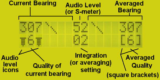
The arrangement of the main
display of this new
firmware showing dual graphical and numerical bearing
displays:
This
display is identical for both the Montreal II and III
versions. Go to the Operating
Manual
page for more information.
New graphical compass rose. The original
Montreal Doppler
II code displayed a clever, but difficult-to-decipher graphical
32
point
compass rose display. The intent was to provide a visual
representation
of the bearing of the received signal with respect to the
current
location.
The problem is that with the 16 character, 2 line display, the
compass
rose was extremely "squashed" and it took more than a quick
glance to
try
to figure out the bearing. This new firmware provides a
smaller,
but more intuitive compass rose showing the current bearing in a
form
that
resembles an analog clock (but with only a minute hand...)
This
new
display only displays 16 points of the compass, but owing to the
small
size of this display, more resolution would be of questionable
benefit.
Sliding average. Also displayed is a sliding
average
consisting of up to 32 readings (including the current
one.)
Because this average is updated with each new reading, a high
average
setting does not slow the update rate like the integration
does.
Also, because it calculates the average based on the amplitude
vectors
of the original readings, its operation has much the same effect
as the
8-capacitor roanoake filter - a real benefit to the users
of an
Doppler II without the switched-capacitor filter!
Doubled update rate. In the original
Montreal
Doppler
II code, new readings were not being taken while the display was
being
updated, most notably when the integration was set to 1.
This has
been changed so that up to 20 readings per second are available
on the
serial port and/or the Compass Rose display. One may
select
between
the current reading or the average reading to be output on the
serial
port.
A dual compass rose. Actually,
there
are two
compass roses on the display. The one of the left displays
the current
bearing while the one on the right displays the sliding
average
of past readings as long as they are above the minimum quality
value.
This additional display can provide the following benefits:
If the signal is very noisy and seemingly random (as is
often
the case
when operating mobile amongst urban clutter) an averaged
reading can go a long way towards being able to determine a
likely
bearing.
Being that this average bearing is weighted according to
quality, poor
bearings won't affect the average as much as good, solid ones.
A smaller integration rate may be used. Often, the
minimum
integration
(e.g. none) is more than adequate. In this setting,
about 20
readings
per seconds are displayed, completely updating the "average"
about 1.3
times per second. Because this average is sliding,
it is also updated at the same 20 readings per seconds - but
the result
is significantly smoothed.
Because the averaging is only done on "good" quality signals
(those
above
the selected "minimum" quality level) it will "freeze" the
display when
the signal disappears, showing the average. Because the
original
Doppler II would continue to process the signal for a short
time after
it had disappeared (owing to the integration) it was likely
that the
last
reading displayed was likely erroneous, having been based on
the
squelch
noise burst and having nothing to do with the original
signal.
This
"average" display mitigates this problem, as only a few of the
last
(erroneous)
readings are contributing to the overall average. (Note:
The
audio
level detect modification for the Doppler II noted
below improves
this
even more!)
Dual numerical displays. For both
displays,
the bearing and signal quality is displayed. In
addition
to
the "sliding average" bearing, the averaging display also shows
the
"average"
quality for that same bearing. In addition, the current
integration
rate is displayed, along with either an "S-meter" reading (if
connected
to the receiver) or audio input level - selectable by the user.
Support for a "raw" audio level meter.
One
of
the overlooked
features on the Montreal Doppler II unit (something corrected
with the
Montreal Doppler III) was a means of detecting the "raw" audio
level.
On the original Montreal Doppler II code, the audio level is
computed
from
the processed input data - but this is rather slow to respond,
particularly
if a higher integration rate is used. The result of this
(as
mentioned
above) is that it takes a moment to detect that an input signal
has
disappeared
and to stop processing, the result being is that the final
bearing(s)
may
be bogus. Being able to measure the audio level as it
comes from
the audio audio peaking filter (the first-stage filtering,
outside the
microprocessor) allows much faster response to the disappearance
of
audio.
This means that the most recent good reading may be "frozen" on
screen
when the signal disappears and the squelch closes. This
input
audio
level is displayed as a graphic on the screen - along with the
"gating"
status (e.g. whether or not the audio input is too low to allow
display
of a reading) with the "gating" threshold being
adjustable. Note
that
for
the
Montreal Doppler II, this feature requires a simple
modification of the main board involving cutting of two
traces, the
installation of one jumper, and the addition of 3 resistors, a
diode,
and
capacitor.
Differential outputs for 4 antennas. In
addition to
the 4, 6, or 8 antennas (and selectable drive polarity) of the
original
Montreal Doppler II unit, when 4 antennas are selected, the
"other" 4
output
pins (the connections for antennas 5-8) provide an
opposite-polarity
drive
signal for differentially-driven antenna switches.
Vector-based "quality" calculation. The
quality
of
the signal is now based on the quality of the resolved
directional
vector
itself rather than just amplitude. This permits better
quality
assessment
of signals that are noisy and/or "multipathy" and thus improve
the
likelihood
of rejecting signals with poor quality and prevent their
contribution
to
the calculated direction.
Support for a Compass Rose display without
using
the
RS-232
port. A larger compass rose (Pelorus) is a
highly
desirable
accessory - which is precisely why the newer Montreal Doppler
III has
one
integrated with it. Originally, the Montreal Doppler II
could
"drive"
an external compass rose only via the serial port, but it would
be nice
to not have to tie it up the serial port this way
-
especially
if one wishes to put the compass rose in the same enclosure AND
use an
external computer/GPS receiver. This new code can provide
a
synchronous
data output to drive a compass rose like the one used on the
Montreal
III
unit - and it is, in fact, compatible with the original
Montreal
Doppler
III compass rose displayand the updated
firmware for the Montreal Doppler III's compass rose.
Note
that
this feature requires a simple modification of the Doppler II's
main
board (simple cutting) and, of course, the addition of a compass
rose
display
like that used with the Montreal
Doppler III. One may select either the current reading or
the
average
reading to be displayed on the compass rose.
Improved GPS multiplexing. NMEA
sentences
from
a GPS
receiver are "passed through" the serial port, allowing the user
to
have
both devices on a single serial port. The original
firmware
"froze"
while it waited to synchronize to the incoming GPS data.
In this
firmware, the GPS passthrough multiplexing is completely
transparent to
the user and does not, under any conditions, affect normal
operations.
Additionally, support for 19200, 38400, 57600, and 115200 baud
has been
added.
"Adaptive Filtering"
for a
switched-capacitor filter.
This feature allows a very fast response to brief signals - even
if the
filter is set to respond "slowly." If an 8-capacitor
"Roanoke-type" switched capacitor filter is present (as on
the
Doppler III, or if
one is added to the Doppler II) an additional
modification
will automatically switch this filter to a "fast response" mode
when it
disappears. This allows two things to happen:
Remenants of the "old" signal are quickly removed from the
filter, allowing it to start "fresh" when a new signal
appears.
When a new signal appears, it is not affected by previous
"history."
Within 50-100 milliseconds of the new signal being detected,
the Roanoke filter is returned to its orginal settings.
At this
instant, the Roanoake filter is already "pre-loaded" with some
bearing
information about the "new" signal and from that point on, the
original
setting of the filter (as set by the "damping" control, if
present)
will take over, providing the "slow" filtering. This
allows a
very fast response to the appearaince of a "new" signal - even
if the
damping is set to provide a "slow" response.
Use of the "alternate" firmware on the
Montreal
Doppler
II:
Note:While it is possible to simply "plug in"
the
alternate firmware into a Doppler II with no modifications at
all,
the
use
of
some of the features on the
Montreal
Doppler II require some simple board modifications - go the Doppler
II Modification page for more information.
With the
alternate firmware, if all of the listed modifications are
performed,
the feature set of the Doppler II is the same as that of the Doppler
III.
Perhaps the most useful feature for users of a Doppler II that
haven't added the
switched-capacitor filter is the addition of the sliding
average. As mentioned above, this simulates, in
software,
much of the effect of the 8-capacitor "Roanoake-style" switched
capacitor filter present in the Doppler I and Doppler III. To
be
certain, the most flexible combination is to add such a filter to
the
Doppler II so that you have both. If you have a Doppler II without
the 8-capacitor switched-capacitor filter you will notice an
immediate
benefit in terms of filtering.
Use of the "alternate" firmware on the
Montreal
Doppler
III:
Because of the similarity between the hardware on the Doppler II and
Doppler
III units, it wasn't too difficult to modify the code to be able to
work
with either platform, the desired hardware configuration being
selectable
at compile time. This new firmware does everything that its
Doppler
II equivalent does as well as taking advantage of the Doppler III's
added
hardware:
Supports the Compass Rose display. With the current
firmware, the current reading, the averaged reading, or even both
may be displayed simultaneously.
Utilization of the Doppler III's audio level metering
capability.
This audio level is shown on the display using an icon.
"Gating"
of the readings (e.g. starting and stopping) based on the audio
level
is
also supported.
A reworked menu interface. While the Doppler II has 4
buttons
used
to navigate around the menus, the Doppler III has a
potentiometer and
one
button: This change necessitates a different method of
selecting
and changing menu items.
When in the normal display mode, the pot is used to adjust the
integration
rate (or, if so-configured, the amount of averaging) and the
button
sends
the current reading (selectably the current reading or the
average) out
the serial port, if enabled.
On other menus, the pot is used to move a cursor that selects
menu
items
and the button is used to change the selected item.
Because of the ease of adjustment when using the
potentiometer, a
wider
selection of integration/averaging settings is available from
the main
display
Serial output and/or GPS passthrough. Just like the
original
Doppler
II firmware, one may select a continuous output stream of
bearing/quality
data, have the data sent on a selectable timed interval, or
configure
to manually send the bearing at the push of a button.
Optionally,
data from a connected GPS receiver may be passed through.
The
serial
bearing data being output (in "Agrelo" format) may be either the
current or the averaged reading.
Preliminary operating instructions for this firmware
may be found on the Operating
Manual
page.
For information about obtaining the
chips
containing the described firmware, please refer to this web
page:
This code was originally based on that of the original
Montreal
Doppler
II DF unit by the late Jacques Brodeur, VE2EMM, and full credit
is given to him
for this fine work. Because the additional modifications
are my
own
and were not done with his involvement!
Although good faith efforts have been made to make certain
that
the
operation of the hardware/firmware is as described, it is
possible that
"undocumented features" (bugs) may be present: It is
through
testing,
use, and feedback from the users that projects such as this may
be
improved,
and the user is asked to be understanding of this fact.
This
firmware
is strictly intended only for non-commerical amateur-radio use
and any
other use is in violation of applicable laws.
Additional note: Neither the author or UARC
officially
endorse any vendors mentioned above or assume any responsibility
for
the
use of the devices/products described herein. The level
and
satisfaction
of performance of any of the above is largely based on the skill
and
experience
of the operator. Your mileage may vary.
Do you have any questions on this or other DF-related
topics? Go here.